All-In-one hybrid energy system ESS GE-F60 50kW/60kWh
$61.26
$101.08
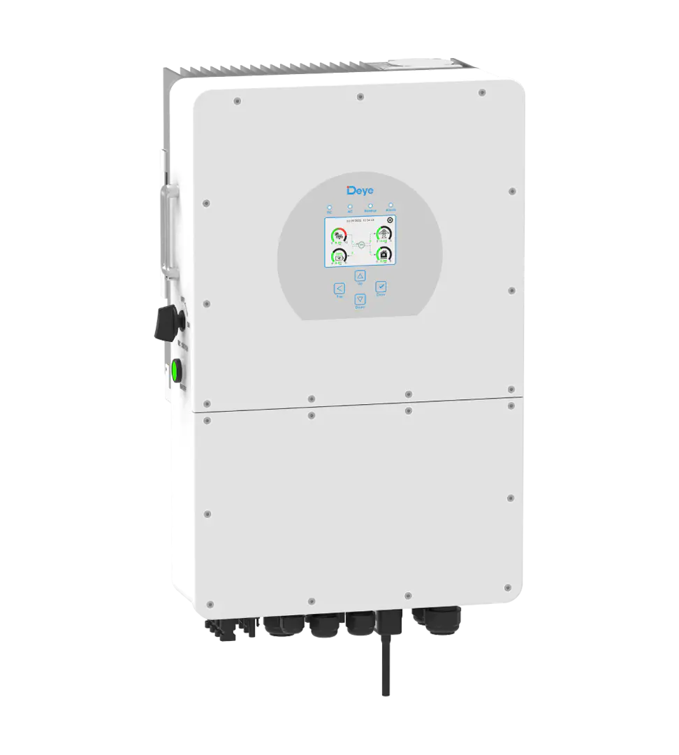
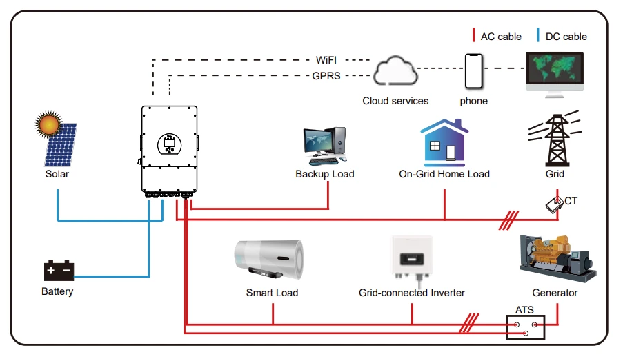
Description High Voltage All-In-One Hybrid Deye ESS GE-F60 (50KW/60KWh), Price and Specifications Rated power operation the maximum temperature of the battery is less than 40℃ EMS, hybrid inverter and BMS integrated technology, power supply redundancy design, support black start function, Off-grid operation, etc Suitable for high-rate cyclic charging and discharging scenarios Lithium Iron Phosphate (LFP) Battery, The battery pack and system adopt an aerosol fire extinguishing solution Combustible gas, smoke and temperature detection, system active exhaust, and fire alarm Supports battery expansion, with a maximum capacity of 360KWh System, Inverter, Battery Specification Nominal Output Power / UPS Power (W)50000AC Output Frequency and Voltage50/60Hz; 3L/N/PE 220/380, 230/400VacGrid TypeThree phaseEnergy Configuration (kWh)61.4Dimension (W x D x H, mm)735x1050x2250(no contain inverter)Weight Appr. (kg)950(battery) 80(inverter)AC Output Rated Current (A)75.8Battery Operating Voltage (V)500 ~ 700Max. charging/discharging efficiency91�ttery ChemistryLiFePO4IP Rating of EnclosureIP55Installation StyleFloor-MountedWarranty10 yearsInverter Technical SpecificationMax. PV Input Power (W)65000Max. PV Input Current (A)36 36 36 36Rated PV Input Voltage (Vdc)600Peak Power (off-grid)180MPPT Voltage Range (Vdc)150-850Max. PV Short-circuit Current (A)55 55 55 55Number of MPPT4Peak Power (off grid)1.5 time of rated power, 10sPower Factor0.8 leading to 0.8 laggingTHD<3� injection current (mA)<0.5%lnDisplayLCDOperating Temperature Range (℃)-40~60 ( >45℃ derating)Relative Humidity15% ~ 85% (No Condensing)Dimension (W x D x H, mm)527x294x894Inverter CommunicationCAN, RS485, WIFI, ETHSafety EMC / StandardIEC/EN 62109-1, IEC/EN 62109-2, IEC/EN 61000-6-1, IEC/EN 61000-6-2, IEC/EN 61000-6-3, IEC/EN 61000-6-4Grid RegulationVDE4105, IEC61727 / 62116, VDE0126, AS4777.2, CEI 0 21, EN50549-1, G98, G99, C10-11, UNE217002, NBR16149 / NBR16150Max. Efficiency97.6%MPPT Efficiency99.9�ttery Technical SpecificationBattery Module Nominal Voltage (V)51.2Battery Module Energy (kWh)5.12BMS CommunicationCANBattery Module Dimension (W*D*H mm)440x570x133Battery Module Weight (kg)44Operating Temperature RangeCharge: 0~55℃ / Discharge: -20℃~55℃Cycle Life≥6000 (@25℃±2℃, 0.5C/0.5C, 70%EOL)Battery Module CertificationCE, IEC62619, IEC62040, UN38.3 Product expansion MAX: 50kW/360kWh Product introduction ① Air conditionerCooling the ESS system② Smoke detectorA device used to detect smoke in a fire and sound an alarm when smoke is detected.③ Heat detectorA device used to measure temperature and sound an alarm if it detects excessive temperature.④ Travel switchCheck whether the ESS system door is closed.⑤ InverterA device that converts direct current generated by a battery into alternating current.⑥ Aerosol fire extinguishing deviceWhen the ESS is detected to be on fire, aerosol is emitted to extinguish the fire. ① FanEmission of combustible gas② Combustible gas sensorDetect combustible gases③ Serial relayControl system④ Terminal lineFor connecting cables⑤ Switching Mode Power SupplyPower source⑥ Temperature and humidity sensorUsed to measure ambient temperature and humidity⑦ Miniature circuit breakerControlled power-on and power-off⑧ RelayAutomatic regulation, safety protection, conversion circuit⑨ Water immersion sensorCheck the ESS for water leakage⑩ Terminal lineConnect external cables ① Aerosol fire extinguishing deviceWhen the pack is detected to be on fire, aerosol is emitted to extinguish the fire.② Battery moduleProvides electrical energy storage and output③ CCSCells Contact System④ Air inletCold air inlet⑤ Battery negative-/⑥ Battery positive /⑦ FanPromote internal and external air flow⑧ BMUBattery monitoring ① B-Connection position of the common negative pole of the battery② B Connection position of the common positive pole of the battery③ Air switchUsed to manually control the connection between the battery rack and external devices④ ALRM light indicatorBattery system fault alarm indicator⑤ HV light indicatorHigh-voltage hazard indicator⑥ PCS-Connection position of PCS negative pole⑦ PCS Connection position of PCS positive pole⑧ USBBMS upgrade interface and storage expansion interface⑨ OUT COMConnection position with next HVB-100A 750V communication output⑩ IN COMConnection position with previous HVB-100A 750V communication input⑪ PCS COMCommunication interface with charging and discharging equipment⑫ STARTA start switch of 12VDC power inside the high-voltage control box⑬ COMM1Communicative connection with the cabinet⑭ COMM2Communicative connection with the first battery module; and providing 12VDC power for the first battery module.
Photovoltaic Systems